Modeling of a 3D parametric log cabin tutorial We will create a model of a parametric log house. To keep the lesson simple, we will introduce just three parameters: the radius of the log cross-section, the width of the house and the length of the house. In real assignments, the number of parameters will, of course, be much greater, but for educational purposes, introducing new parameters in this example will not teach us anything new. Thus, we need to build a model of a house that will be reconstructed using a single function:
|
|
void Build( sgFloat log_size, sgFloat houseSizeX, sgFloat houseSizeY );
|
|
To begin, lets initialize the core library. You need to do this once in the main thread before using the sgCore function for the first time:
|
|
sgInitKernel();
|
|
Our first step is to construct the log cross-section. In order for the logs to form a more or less stable structure, rather than simply lying one on top of the other, we will create the shape of the cross-section from two arcs, rather than a circle:
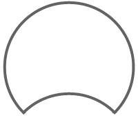
You can create the log from this cross-section in two ways: either by creating the flat cross-section and applying an extrusion operation on the flat shape, or by creating two cylinders with identical radii, displacing one of the cylinders and applying a Boolean subtraction operation. Since the extrusion operation is faster than the Boolean subtraction, lets use the first method.
We will create the cross-section from two arcs. For the logs to fit tightly against one another, these arcs must have identical radii:
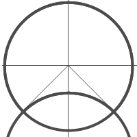
To create the two arcs, we need to calculate the points of intersection of two circles with identical radii. This radius is one of the parameters of our model : the function for creating the cross-section of the log will therefore have one input parameter: log radius.
|
|
void BuildLogSection( sgFloat log_size );
|
|
Lets create the first arc of the cross-section from three points:
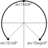
Let the angle that determines the intersection of these two circles be 45 degrees. The points that define the first arc will then have the following coordinates:
|
|
SG_POINT arc1BeginP = { log_size * cosCalc, -log_size * sinCalc, 0.0};
SG_POINT arc1EndP = { -log_size * cosCalc, -log_size *sinCalc, 0.0}; SG_POINT arc1MidP = { 0.0, log_size, 0.0}; |
|
Where log_size is the radius of the log, and sinCalc and cosCalc are the sine and cosine of the angle that, we decided, will equal 45 degrees. By setting different angles, we can obtain many different versions of the cross-section formed from two arcs.
Lets create the arc structure from these three points:
|
|
SG_ARC arc1;
arc1.FromThreePoints(arc1BeginP, arc1EndP, arc1MidP, false); |
|
The first three arguments are the calculated points, and the final argument specifies whether or not to invert the arc defined by the three points. If this parameter is set to false, the mid-point of the arc will lie on the arc we are creating; if it is set to true, an arc will be created, that completes the circumference of the arc created in the first way.
We will create the second arc in a different way: from the two end-points, the normal line to the arc, and the radius. The end-points of the second arc will coincide with those of the first arc, the normal line to the flat plane of the arc is the Z-axis, i.e. vector (0, 0, 1), and the radius is the same as that of the first arc, i.e. log_size. Lets build the structure of the second arc:
|
|
SG_ARC arc2;
arc2.FromBeginEndNormalRadius(arc1BeginP, arc1EndP, zAxe, log_size, false); |
|
Next, we need to create the actual objects of the geometric core: the sgCObject delegates. For the arcs, these will be the objects of class sgCArc. Since we will ultimately build the cross-section from these arcs, we will save our arcs immediately to an array:
|
|
sgCObject* acrsObjs[2];
acrsObjs[0] = sgCArc::Create(arc1); acrsObjs[1] = sgCArc::Create(arc2); |
|
And we will create the cross-section itself, which will ultimately be used to build the log:
|
|
m_log_section = sgCContour::CreateContour(acrsObjs, 2);
|
|
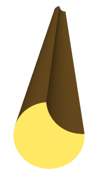
Once the cross-section has been built, we can create the log. Since we need to create logs of different lengths, we will create a function to extrude our cross-section by a specified length.
|
|
sgC3DObject* BuildLog(sgFloat logH);
|
|
We are creating a flat shape in the XOY plane, and so we will extrude the cross-section outline along the Z-axis (the plane perpendicular to the cross-section):
|
|
SG_VECTOR extrVect = {0, 0, logH};
sgCObject* logObj = sgKinematic::Extrude(*m_log_section, NULL, 0, extrVect, true); |
|
The first argument of the extrusion function is the cross-section that we are extruding; the second argument is the array of holes in the object being extruded (also the flat contours that lie within the outline); the third argument is the number of holes. Since there are no through-holes across the whole length of the log in the logs we are using to construct the house, in our case, these two arguments are null. The fourth argument is the vector of extrusion: for us, this is directed along the Z-axis and has length logH, an argument of the log creation function. The final argument determines whether the object created will be sealed together as a solid body or we will simply create the outer surface of the extrusion. In other words, do we need to create end caps or not? For us, this is set to true.
Lets create the first log with a specific length and add it to our scene:
|
|
sgGetScene()->AttachObject( BuildLog(houseSizeX) );
|
|
On running the program, we will see an empty scene. Where is the log???
In fact, the log has been created and will be drawn if, instead of using the triangle array of the object to draw it, you use its wireframe model. Our log does not yet have any triangles, and therefore, we could not see anything.
In order for the 3D object to be presented in triangle form, the object needs to be triangulated. This can either be done automatically for all 3D objects created, or manually for each object. For automatic triangulation, the flag must be enabled:
|
|
sgC3DObject::AutoTriangulate(true, SG_DELAUNAY_TRIANGULATION);
|
|
The second argument is the triangulation type. The types of triangulation are described in more detail in the documentation.
There is one point to note here. Triangulation of very complex objects can take some time, and triangulation is not required to use and work with objects: it is necessary only in order to visualize the final result. Therefore, if you are building complex objects as an intermediary stage, you should turn off automatic triangulation and triangulate the final result that the user will see. Since we will have several complex operations before we reach our final result, we will turn off automatic triangulation and triangulate manually only those objects that we really need to visualize.
Therefore, we will modify the construction of our log a little:
|
|
sgC3DObject* log1 = BuildLog(houseSizeX);
log1->Triangulate(SG_DELAUNAY_TRIANGULATION); |
|
This is what we get:
The next step is the construction of the grooves for each log created. The grooves are the indentations in the log in the places where the log will be set against another log. We will construct grooves in our logs where they join the other logs on which they lie, taking into account the typical overhang for log houses.
To do this, we will expand our log construction function, introducing new parameters:
|
|
sgC3DObject* BuildLog(sgFloat logH, bool withGroove, sgFloat logH, bool withGroove, sgFloat groove_size, sgFloat grooveShift);
|
|
withGroove - flag indicating whether a groove needs to be made groove_size - groove radius (equal to the radius of the log) grooveShift - offset from the end of the log where the groove will be cut. There will be two grooves, one from each end of the log.
To cut the grooves, we will use Boolean subtraction. For the sake of speed, the subtracted object will be a cylinder. Another log could be used, of course, but given the logs will intersect in such a way that, relative to one another, they can be considered cylinders (the notch formed by the second arc of the extruded cross-section does not take part in the groove process), we will subtract a cylinder.
Lets create two cylinders with a radius equal to the radius of the log and any length (the length of this temporary object is irrelevant, and has no impact on either the working speed or the result). The most important thing at this step is to position these temporary objects correctly in the space. Since our log has a base in the XOY plane and is extended along the Z-axis, we must position these temporary objects in a corresponding way. As primitive objects, the cylinders are also created in the XOY plane, with a center at the origin, and extended along the Z-axis. We must, therefore, first rotate our temporary objects about the Y-axis, then displace them to take into account the depth of the groove (this will be half the thickness of the log, which happens to be our log_size parameter), and the offset from the end of the log. The creation of these temporary objects in this way will look like this:
|
|
if (withGroove)
{ sgFloat cylH = 10*groove_size; sgC3DObject* cyl1 = sgCreateCylinder(groove_size, cylH, 24); cyl1->InitTempMatrix()->Rotate(zeroP, yAxe, 90.0*M_PI/180.0); SG_VECTOR transVect = {-cylH/2, -groove_size, grooveShift}; cyl1->GetTempMatrix()->Translate(transVect); cyl1->ApplyTempMatrix(); cyl1->DestroyTempMatrix(); sgC3DObject* cyl2 = sgCreateCylinder(groove_size, cylH, 24); cyl2->InitTempMatrix()->Rotate(zeroP, yAxe, 90.0*M_PI/180.0); transVect.z = logH-grooveShift; cyl2->GetTempMatrix()->Translate(transVect); cyl2->ApplyTempMatrix(); cyl2->DestroyTempMatrix(); } |
|
These objects do not need to be triangulated, but lets do it anyway and add them to the scene, just to see whether we have positioned them as follows:
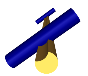
Excellent. The objects are positioned as required. Lets remove the triangulation of these objects from the code, as we will not add them to the scene.
Next, we need to use Boolean subtraction to get a log with grooves.
To begin with, we will subtract the first temporary object. Since as a result of the Boolean subtraction, a group is created, we need to get rid of this group, delete the group object, and reassign the log indicator to the first (and only) object in the deleted group. We must also remember to delete the temporary cylinder as well as the old log object, as we do not need these any longer:
|
|
sgCGroup* boolRes1 = sgBoolean::Sub((const sgC3DObject&)(*logObj), *cyl1);
int ChCnt = boolRes1->GetChildrenList()->GetCount(); sgCObject** allChilds = (sgCObject**)malloc(ChCnt*sizeof(sgCObject*)); boolRes1->BreakGroup(allChilds); sgCObject::DeleteObject(boolRes1); sgCObject::DeleteObject(logObj); logObj = allChilds[0]; sgCObject::DeleteObject(cyl1); |
|
We will do the same with the second temporary cylinder:
|
|
boolRes1 = sgBoolean::Sub((const sgC3DObject&)(*logObj), *cyl2);
ChCnt = boolRes1->GetChildrenList()->GetCount(); allChilds = (sgCObject**)malloc(ChCnt*sizeof(sgCObject*)); boolRes1->BreakGroup(allChilds); sgCObject::DeleteObject(boolRes1); sgCObject::DeleteObject(logObj); logObj = allChilds[0]; sgCObject::DeleteObject(cyl2); |
|
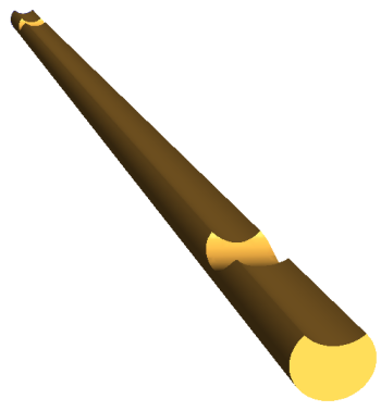
Following these two operations, we will get the following result:
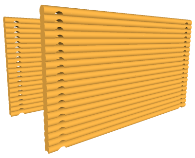
The next step is creating the walls. Essentially, this step does not introduce anything new: we just need to create the required number of logs and position them in the correct places. We will say only that to create identical logs, we will use the object cloning function (Clone()), rather than creating them from scratch. We will omit the description here of where each log should be positioned, and simply show the steps to construct the walls:
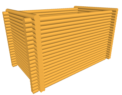
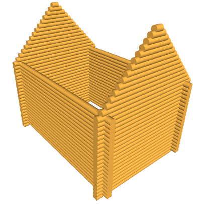
So, the walls are built. Now we have a complete parametric model of the basis of the house, which fully meets the requirements for joining together the logs: a test of rigid-body object operations. This means that our model of the house is created not just as a representation, but in full accordance with the construction of a real house.
Lets change the parameters a little and see how this will change the house:
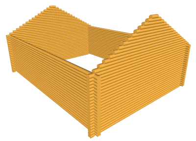
As you see, having the parametric model, you can change just a few numbers and create an infinite number of models with little effort.
The next step is to add windows to the model.
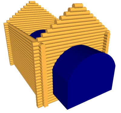
To construct the windows we will use two operations: Extrusion and Boolean subtraction. Of course, real houses usually have rectangular windows, but we want to make the windows an unusual shape; so instead of simply using a temporary box (as we could in the case of a rectangular window), we will apply extrusion to a particular curved cross-section.
So, to begin with, lets create this cross-section. The functions for creating and extruding the cross-section are analogous to those we used to create the log, therefore we will not focus our attention on these. Once we have extruded the cross-section and positioned it in the correct place, we get the following:
We will subtract our window from the logs of the first wall. Lets, therefore, turn off triangulation for these in their construction function, and triangulate the results once the subtraction for the windows has been applied. To subtract the window from the wall, we need to subtract the window object from every log of the wall. We can make this more optimal, as we know precisely where each log is positioned and where the window is positioned, and we can apply the Boolean operation only to those logs with which the window intersects. But we will go with the result of the Boolean subtraction. If the result is null, this means the objects do not intersect. We must also consider that, in this case, the result of the Boolean operations may consist of several objects (the window divides the log in two). We must also remember after all Boolean operations to delete the temporary object and old logs:
|
|
size_t oldCnt = m_walls[0].size();
for (int i=0;i < oldCnt; i++) { sgCGroup* boolRes = sgBoolean::Sub(*m_walls[0][i], *winObj); if (boolRes) { int ChCnt = boolRes->GetChildrenList()->GetCount(); sgCObject** allChilds = (sgCObject**)malloc(ChCnt*sizeof(sgCObject*)); boolRes->BreakGroup(allChilds); sgCObject::DeleteObject(boolRes); sgGetScene()->DetachObject(m_walls[0][i]); sgDeleteObject(m_walls[0][i]); for (int j=0; j < ChCnt; j++) { ((sgC3DObject*)allChilds[j])->Triangulate(SG_VERTEX_TRIANGULATION); sgGetScene()->AttachObject(allChilds[j]); } m_walls[0][i] = (sgC3DObject*)allChilds[0]; for (int j=1;j < ChCnt;j++) m_walls[0].push_back((sgC3DObject*)allChilds[j]); free(allChilds); } else m_walls[0][i]->Triangulate(SG_VERTEX_TRIANGULATION); } sgDeleteObject(winObj); |
|
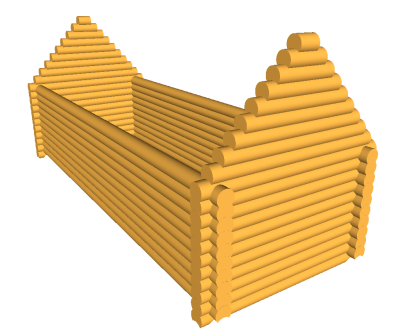
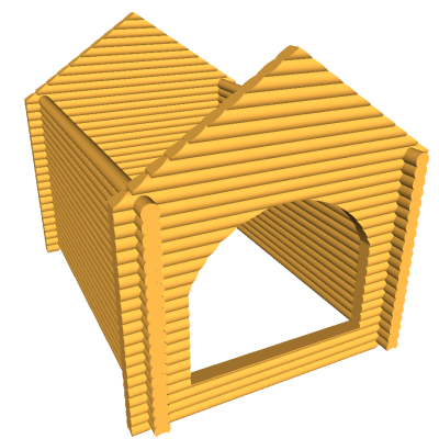
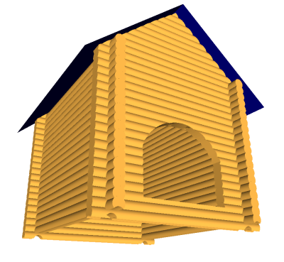
After this, we get a model of the house with a window:
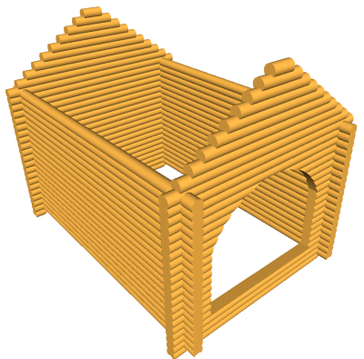
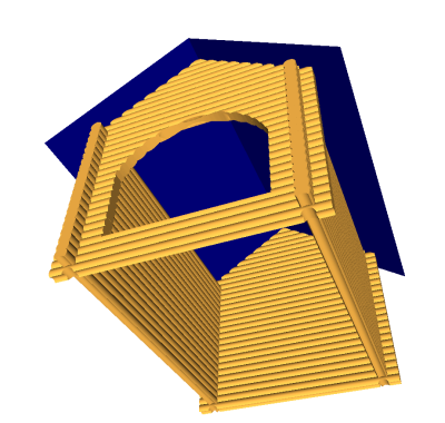
One final step remains, to add the sloping roof. We will do this in two steps: first, we will trim the logs that will touch the roof surface, then we will create the roof itself.
To begin, lets delete all the triangulation commands for all the logs created earlier. To create the roof, truncation will be applied to all the logs by the roof surface, i.e. Boolean subtraction. We will triangulate all the results of these subtractions.
So, using the extrusion operations, lets create the temporary object to truncate our logs underneath the roof surface:
Then, lets subtract this temporary object from all the logs, just as we subtracted the window from the logs of the first wall:
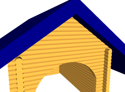
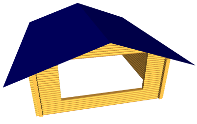
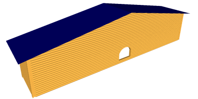
Finally, we need to create the roof surface. Lets use the extrusion operation again for this. After this, we have the following completed model of our log house:
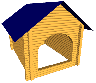
As well as an infinite number of variations of this model, by way of adjusting the parameters:
|

| SGCORE | TUTORIALS | ORDER | CUSTOMERS | CONTACT |
